The Camera Slider
Introduction
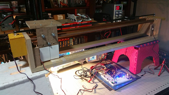
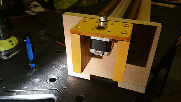
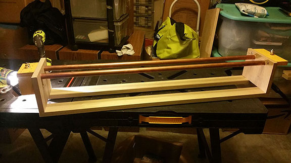
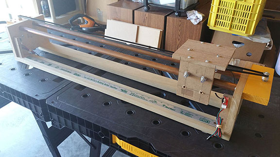
I would like to start by stating that I have never done carpentry work, so for me it was kind of a challenge because after seeing some other Slider websites, the first thought I had was my desired to build something similar, my second thought was “I don’t want to pay someone to build it for me” and my third thought was to go to Home Depot. Anyway, long story short and after a considerable amount of money spent on power tools, you can see in Figure 1 below my Camera Slider, and even though it is not finished I decide to start building its web page as a way to have a recording history of the whole building process. The whole purpose, and that goes to most of the projects I develop, my intention is to get the knowledge first-hand, the know-how of building a physical device, to then put together the electronics, to finally writing the computer programs to glue all together and that is a lot of fun.
Figure 1: The Camera Slider.
The whole process of creating the Slider and developing the Software has been exciting but pretty much standard, meaning nothing out of the ordinary, with the exception of precision, which is the one thing that gave, and keeps giving me, issues. See, after seeing the slider for the first time my thought was to build a plotter of some sorts, a 3-axis Cartesian system, where I can specify, via software, an x and y position, give the motor(s) the command and the time to get there, then do a move in the z-axis, which at that point the task the plotter was designed for would take place, like drilling a hole, doing a welding point, or just simply drawing a line or a series of dots, who knows since the number of possibilities or tasks at hand are pretty much open at that point. So precision it is and there is where I am stuck right now. I mean a Camera Slider does not require precision as long as the moves are smooth, on the other hand, a plotter, or a slider, made with the purpose of doing some repetitive tasks, requires precision every time the task is done like drilling a hole hundreds of times in the same exact spot with a minimum, if not zero, margin of error.
I am working on a couple of different possibilities to fix the precision issue, including getting a better Stepper Motor to begin with, but in the mean time I am developing a Camera Slider just to have some fun.
The C-Sharp Interface
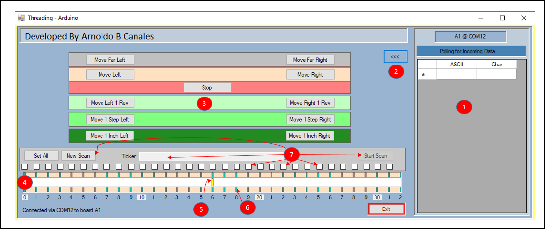
On my previous project I created an Arduino program interfaced with some buttons to move the motor left and right, furthermore, I added two more buttons to simulate the motor reaching the far left and right limits. I also created a simple C-Sharp interface. Both of those programs plus the electronics became the foundation for this more elaborated project as you will see. My intention is to demo the programs and this (incomplete) part of the slider on this web page, then on a second web page, I will develop and demo the Pan and Tilt part of the camera slider. So with that as a plan, observe below a picture of the C -Sharp interface and the different controls it sports to command the Stepper Motor.
Figure 3 below shows the C -Sharp Interface I developed thinking about a Plotter; a Camera Slider device wouldn’t require such level of complexity or elaboration but since I am already here I think I can use it to test, calibrate, and benchmark this device so bear with me.
Figure 3: The C-Sharp Interface Program.
| Description | |||
|---|---|---|---|
| 1 | Polling Information Area – Feedback information coming back from the Arduino Controller. | ||
| 2 | Button to expand/collapse the Polling Information Area. | ||
| 3 | Commands to move the motor via buttons. | ||
| a) | Go Far Left/Right. The motor moves Left/Right until the Limit Switch is triggered. | ||
| b) | Move to Left/Right. Pretty much the same as above. Both of these commands can be stopped at any time by pressing the Stop button. | ||
| c) | Move Left/Right one (1) whole revolution. | ||
| d) | Move Left/Right one (1) step or 1/8th of a degree. The angular displacement for this motor is 1/8th of a degree per step needing 100 steps to reach half a revolution. | ||
| e) | Move Left/Right one (1) inch. | ||
| 4 | The Slider with 32 marks spanning from 0 to 31 inches. | ||
| 5 | Yellow Indicator. This indicator displaces at the same rate the motor moves the camera harness. User is able to drag-n-drop it for the motor to go to that point. | ||
| 6 | By clicking the green slots, the motor gets the command to displace the harness to that position. | ||
| 7 | Scan Option. This option allows to create repetitive tasks by marking where the user wants the harness to be displaced, wait a few seconds, then move to the next point, and so on and so forth. Do the same movement any n given number of times. | ||
Note: “Move Left/Right” means the motor rotating clockwise/counterclockwise which translates on the harness to make left/right displacements.
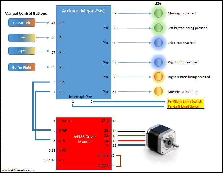
Figure 4 below shows the complete wiring diagram for this project. I am actually using two power supplies, one at 12.0 volts to power the motor and a second one at 5.0 volts to feed all the electronics. I can always rely on power provided by the Mega 2560 board but I prefer an external power supply just for the electronics. I would like to emphasize the importance of the Limit switches and how, when pressed, they trigger one of the six available interrupts resulting in the execution of the routine(s) shown further down below. It is critical that once the limit, right or left, has been reached, the motor must stop immediately. What I have done via code, once the motor reaches any of the two limits, is to move to a position that I call Left Home and Right Home, which corresponds to inch Zero and Inch Thirty-one respectively. This piece of code provides the ultimate calibration to the device right on the spot.
The Electronics Wiring
Observe below the whole wiring diagram for the Slider, where you can see to the left of the Arduino Mega the inputs to the system and the outputs on the right side, which consist of LEDs and the Motor. Pay special attention to Arduino pins 2 and 3 which are two of the Interrupt Lines I am using to signal Arduino that the motor has reached its far left or right displacement limit. I will be addressing the Interrupt lines with more details further down in the web page.
Figure 4: Complete Wiring diagram.
The Stepper Motor
As I have said before, my intention is to demo the applications and devices I create and not to get into the nitty-gritty details and theory of the electronics or computer devices I am using. There are literally hundreds, if not thousands, of websites explaining with great detail how Stepper Motors work including Wikipedia. With that said, the graphic below shows my contribution to Stepper Motors theory:
Figure 5: The Stepper motor.
As you can see in the figure above the rotor, represented by the yellow arrow, rotates as the coils are powered up to provide the proper polarity of North/South or Positive/Negative. In the example above the steps are provided for clockwise rotation but by inverting the coils polarization sequence, the rotation will go counter-clockwise.
An observation I would like to add here is that what makes stepper motors so attractive and useful is the inherent capacity they have to make small steps every time its coils are properly polarized, hence its name. A common stepper motor will make a 1.8 degrees of angular displacement every time it is energized, at that rate it will take 100 steps to reach 180 degrees or half a revolution, and 200 steps for a full revolution. That is at a full step configuration because some stepper motors are capable of doing micro-steps. That is where the words accuracy and precision are linked to stepper motors. A final observation here, is that the rotation in the figure above is being exaggerated with the purpose of helping the presentation.
The A4988 Motor Driver Module
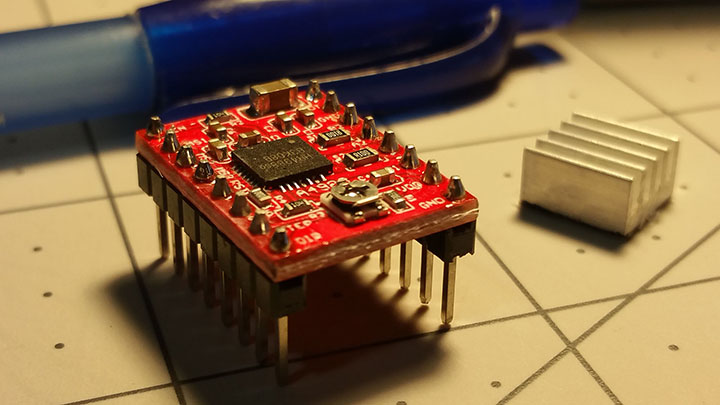
The A4988 Driver Module is full micro-stepping motor driver designed to operate bipolar stepper motors in full, half, quarter, eighth, and sixteenth-step modes. By applying one pulse on the STEP pin drives the motor to make a displacement of one micro-step. Figure 6 below shows the Module and Table 2 shows the Module’s available configurations for the motor to achieve different resolutions.
Figure 6: The A4988 Motor Driver Module.
| MS1 | MS2 | MS3 | Micro-step resolution | Excitation Mode |
|---|---|---|---|---|
| L | L | L | Full Step | 2 Phase |
| H | L | L | Half Step | 1-2 Phase |
| L | H | L | Quarter Step | W1-2 Phase |
| H | H | L | Eighth Step | 2W1-2 Phase |
| H | H | H | Sixteenth Step | 4W1-2 Phase |
Interrupts
Interrupts have been around pretty much since the advent of the Microcomputers, I remember doing hardware interrupts on a PDP-11/40 Mini-computer and also calling routines via interrupts on evaluations boards for the Motorola 6800, the Zilog Z80, and the Intel 8080 microprocessors, that was back in the late 70’s and early 80’s. When it comes to microprocessors and its evaluation boards, things haven’t changed much since then. We have had some progress though, we don’t have to input octal or hex codes anymore (machine language actually) to manually load the program so we have added (or removed) a layer of complexity there with the IDE’s (integrated development environment) available now days. We now have faster clocks running the microprocessors, they are not 2.5 MHz anymore but 16 MHz and faster. The RAM memory has gone from 64 Kb to 256 Kb or even up to 1 Megabyte so plenty of memory there.
But the logic, the concept of a microprocessor fetching codes from memory in on clock pulse to then doing the task in the next clock pulse hasn’t changed at all. It has remained and so has done the concept of interrupts. A Hardware Interrupt it’s actually a pin in the actual microprocessor that when changes its state (in Binary logic from 0 to 1 or vice versa), the microprocessor interrupts what is doing (which is processing codes) to go to a specific address in memory where a piece of code is waiting to be executed and that is pretty neat! The whole concept is so simple yet so powerful that is has been around ever since then and it is not going away, but let me demo how it actually works using a diagram and showing some code.
First of all the Arduino Mega 2560 has six (6) interrupt lines leveled as follows (Table 3):
| Pin Number | Interrupt Name |
|---|---|
| 2 | interrupt 0 |
| 3 | interrupt 1 |
| 21 | interrupt 2 |
| 20 | interrupt 3 |
| 19 | interrupt 4 |
| 18 | interrupt 5 |
These pins can be configured to trigger interrupts when one of the following types of conditions happens (Table 4):
| Condtion | |
|---|---|
| a) | When the pin goes to a low state (LOW) |
| b) | When it changes value (CHANGE) |
| c) | When rising or when it goes from a low state to a high state (RISING) |
| d) | When falling or when the pin goes from high to low (FALLING) |
To achieve this I use a function called attachInterrupt() with the following paramaters (Table 5):
| Parameters | |
|---|---|
| a) | Pin number |
| b) | Function name to be called |
| c) | Type of interrupt |
To terminate or deactivate an interrupt for good, use the detachInterrupt() function. Also while in the interrupt routine, it is a good practice to temporarily disabled interrupts by issuing function noInterrupts(), those de-bouncing any future interrupts while processing an ongoing one. Function interrupts() will reactivated them back up again.
Please visit Arduinos website to learn more about interrupts.
So... wait… what was I talking about??? Oh yes interrupts… sorry I spaced out for a moment.
Figure 7 below shows an emulation of an interrupt and the process followed when it happens. One important factor that I should mentioned is that the Interrupt routine should be short and concise and to the point. It is important to not hangout at the routine for more than the necessary and indispensable time and no more than that. Remember than Interrupts are used to check out crucial aspects of a physical device and to start, as soon as I get into the routine, I am disabling interrupts, so I need to proceed swiftly and re-enabled interrupts ASAP and go back to what the processor was doing before the interrupt happened.
Figure 7: Emulating an interrupt using a graph.
Ok Folks..... I will continue later on the week! tomorrow is Sunday... so.. no work tomorrow!!!
.....
.....
.....
Figure x: The routines below are executed by triggering an interrupt after the proper Limit Switch is reached.
//-------------------------------------------------------------------------------
//Stepper Motor
//FarLeft_Reached Function- Called when Interrupt Pin 2 (INT 0) is triggered.
//-------------------------------------------------------------------------------
void FarLeft_Reached()
{
	noInterrupts(); stepper1.stop();
	//
	mCommandMoveLeftCont = false;
	digitalWrite(LedPin38, LOW);digitalWrite(LedPin39, HIGH);digitalWrite(LedPin40, HIGH);
	//
	mHomeRight = false; mCommandMoveRightCont = false;
	mCommandMoveFarLeft = false; mCommandMoveFarRight = false;
	mCommandMoveLeft1Step = false; mCommandMoveRight1Step = false;
	mCommandMoveLeft1Rev = false; mCommandMoveRight1Rev = false;
	//
	mHomeLeft = true;
	//
	buzzerX(30); interrupts();
}
//-------------------------------------------------------------------------------
//Stepper Motor
//GoToFarLeft Function
//-------------------------------------------------------------------------------
void GoToFarLeft()
{
	if (mHomeLeft == false)
	{
		mHomeRight = false; mCommandMoveFarRight = false;
		digitalWrite(LedPin30, LOW); digitalWrite(LedPin31, LOW); digitalWrite(LedPin32, LOW);
		//
		digitalWrite(LedPin38, HIGH);digitalWrite(LedPin39, LOW); digitalWrite(LedPin40, LOW);
		//
		MoveOneStep(mMoving2Left);
	}
	if (mHomeLeft == true)
	{
		mCommandMoveFarLeft = false;
		digitalWrite(LedPin38, LOW);Goto_zero();
	}
}
//-------------------------------------------------------------------------------
//Stepper Motor
//Goto_zero Function - Postions Motor at the Zero inch (cm)
//-------------------------------------------------------------------------------
void Goto_zero()
{
	for (int i = 0; i <= 7; i++) { MoveOneStep(mMoving2Right); }
	mHomeLeft = false;
	//
	mDialLocation = 0; mStep = 0;
	mLocIndicator = '0';
	//
	Serial.print('~'); //Signal "EoC - End of Command" - Motor Stops.
}
//-------------------------------------------------------------------------------
//Stepper Motor
//FarRight_Reached Function- Called when Interrupt Pin 3 (INT 1) is triggered.
//-------------------------------------------------------------------------------
void FarRight_Reached()
{
	noInterrupts(); stepper1.stop();
	//
	mCommandMoveRightCont = false;
	digitalWrite(LedPin30, LOW);digitalWrite(LedPin31, HIGH);digitalWrite(LedPin32, HIGH);
	//
	mHomeLeft = false; mCommandMoveLeftCont = false;
	mCommandMoveFarLeft = false; mCommandMoveFarRight = false;
	mCommandMoveLeft1Step = false; mCommandMoveRight1Step = false;
	mCommandMoveLeft1Rev = false; mCommandMoveRight1Rev = false;
	//
	mHomeRight = true;
	//
	buzzerX(30); interrupts();
}
//-------------------------------------------------------------------------------
//Stepper Motor
//GoToFarRight Function
//-------------------------------------------------------------------------------
void GoToFarRight()
{
	if (mHomeRight == false)
	{
		mHomeLeft = false; mCommandMoveFarLeft = false;
		digitalWrite(LedPin38, LOW); digitalWrite(LedPin39, LOW); digitalWrite(LedPin40, LOW);
		//
		digitalWrite(LedPin30, HIGH);digitalWrite(LedPin31, LOW); digitalWrite(LedPin32, LOW);
		//
		MoveOneStep(mMoving2Right);
	}
	//
	if (mHomeRight == true)
	{
		mCommandMoveFarRight = false;
		digitalWrite(LedPin30, LOW);Goto_31();
	}
}
//-------------------------------------------------------------------------------
//Stepper Motor
//Goto_zero Function - Postions Motor at the Zero inch (cm)
//-------------------------------------------------------------------------------
void Goto_31()
{
	for (int i = 0; i <= 34; i++) { MoveOneStep(mMoving2Left); }
	mHomeRight = false;
	mDialLocation = 31; mStep = 1240;
	mLocIndicator = 'V';
	//
	Serial.print('~'); //Signal "EoC - End of Command" - Motor Stops.
}
Please check out the videos for this project and let me know your thoughts about it in the comments section below and thanks for visiting!
Videos